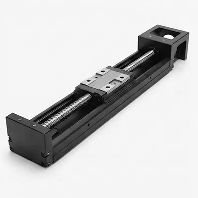
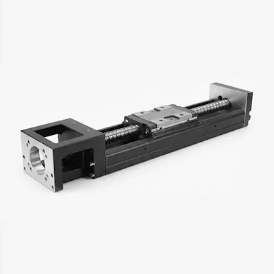
The KK100 represents the engineering pinnacle of U-channel integrated modules. With a width of 100mm, the KK100 is engineered for heavy-duty applications where compromise is unacceptable—whether supporting 100kg workpieces or serving as the crossbeam for large gantry systems, it delivers micron-level positioning accuracy. It stands as the strongest link connecting heavy machinery with precision automation.
| Category | Parameter | Specification / Value |
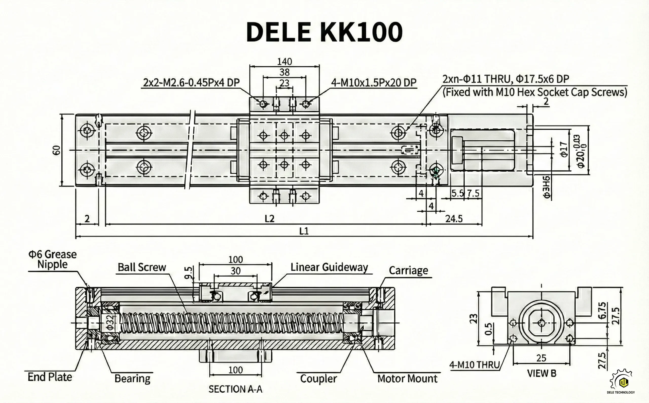
| Basic Dimensions | Module Width | 100 mm |
| Module Height | 55 mm (Rail Base) / 66 mm (With Block) | |
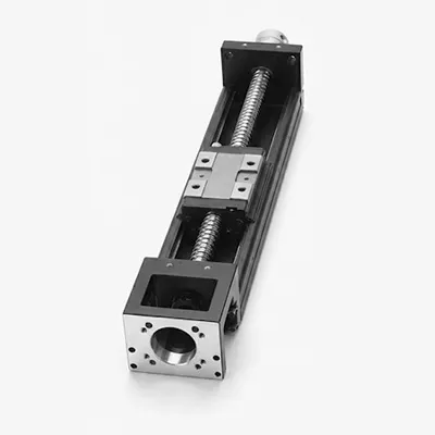
| Rail Type | Ultra-Rigid U-shaped Steel Rail | |
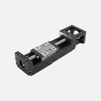
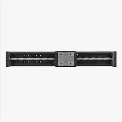
| Block Type | Standard / Double Block Config | |
| Drive System | Drive Mechanism | Precision Ground Ball Screw |
| Screw Diameter | Ø 20 mm / Ø 25 mm | |
| Screw Lead Options | 10 mm / 20 mm | |
| Max. Stroke Range | 200 mm ~ 1500 mm (Customizable) | |
| Performance | Accuracy Grade | Precision (P) / Normal (C) |
| Repeatability | P: ±0.003 mm C: ±0.010 mm |
|
| Max. Speed | Up to 1,500 mm/s (Depends on lead & stroke) | |
| Max. Acceleration | 0.5 G ~ 1.0 G (Depends on load) | |
| Load Capacity | Basic Dynamic Load (Ca) | 38,000 N ~ 55,000 N |
| Basic Static Load (C0a) | 60,000 N ~ 100,000 N | |
| Allowable Static Moment (Mr) | Rolling: 1,500 N•m ~ 3,000 N•m | |
| Allowable Static Moment (Mp) | Pitching: 600 N•m ~ 2,500 N•m | |
| Allowable Static Moment (My) | Yawing: 600 N•m ~ 2,500 N•m | |
| Material & Environment | Main Body Material | High Carbon Steel |
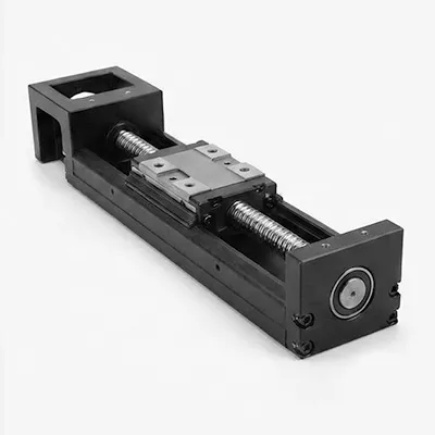
| Motor Compatibility | 750W – 1000W Servo Motor |
In the realm of precision automation, the KK100 linear module stands as an industrial standard. It appears in semiconductor equipment and operates within traditional dispensing machines.
Yet precisely because of its ubiquity, many engineers overlook exploring its deeper characteristics. For professionals like you, merely knowing its stroke and load capacity is far from sufficient. Today, we bypass basic selection manuals to delve into three dimensions—structural rigidity, mounting geometry, and full-lifecycle maintenance—to thoroughly analyze how to truly master this industrial component.
The reason KK100 has become the preferred choice for many non-standard designs lies in its resolution of a classic contradiction: maximizing rigidity within limited space.
It’s crucial to understand that the KK100 base isn’t ordinary aluminum extrusions, but an integrally formed U-shaped steel rail.
Structural Advantage: This U-shaped configuration dramatically increases the sectional moment of inertia. This means that in cantilever or gantry structures, when subjected to lateral forces or torque, the KK100’s resistance to bending far exceeds that of comparable “aluminum profile + guide rail” combinations.
Design Implications: In scenarios with limited space and heavy loads (e.g., Z-axis lifting with 30kg to 50kg loads), prioritize the KK100. Its inherent structural rigidity reduces the need for external auxiliary supports, lowering design costs.
This is where even seasoned engineers can stumble. The KK100’s high rigidity is a double-edged sword: it’s extremely rigid, making it highly sensitive to the flatness of the mounting surface.
When mounting the KK100 on welded frames or unfinished aluminium plates, be vigilant against **geometric twist**.
Hidden Risk: If the base plate’s flatness deviation exceeds 0.05 mm/500 mm, forcing the screws to lock will cause micron-level distortion in the U-channel. This distortion directly transfers to the internal linear guide, abnormally increasing ball preload.
Our countermeasures:
In the selection calculation manual, you may focus more on the “basic rated dynamic load.” However, in actual KK100 applications, failure is often caused not by weight but by torque.
This is especially true when the KK100 is used as a single-arm shaft (X-Y cantilever structure), where the offset between the load’s center of gravity and the slider’s center generates significant torque.
Critical Recommendation: You must rigorously verify the static allowable moment. Although the KK100 has a wide base, a single slider has limited capacity to withstand longitudinal overturning moments.
Solution: If your design involves extended cantilever lengths (e.g., exceeding 200mm), I strongly recommend selecting the Double Block specification. The Double Block not only exponentially increases resistance to moment forces but also effectively suppresses residual vibration during high-speed starts and stops.
During the lifecycle management of equipment post-delivery, the stainless steel dust cover and lubrication system of the KK100 are two high-frequency failure points. Here are two “exclusive tips” known only to field engineers with extensive experience.
The KK100’s dust cover relies on magnetic strips for adhesion. Many maintenance personnel habitually assume that “any friction requires lubrication.”
Your taboo: Absolutely prohibit applying grease to the steel belt’s back surface (the side contacting the magnetic strip). Grease attracts dust particles, elevates the belt, and reduces magnetic adhesion. If the belt bulges during high-speed operation, it becomes highly prone to winding accidents. Ensure this area remains dry and clean at all times.
The KK100’s standard grease fitting is typically located on the slider side. During the design review phase, you must anticipate maintenance scenarios.
Your Solution: If the module’s side space is limited or it’s installed deep within equipment, you must add “nozzle adapters” and “extended oil tubes” to the BOM. Don’t expect field technicians to disassemble the entire unit for lubricant refilling—they cannot do this. The consequence is equipment running dry under friction until it fails.
When you pay attention to these details, the KK100 becomes more than just a purchased component—it becomes the most robust and reliable backbone of your precision system design.
Additionally, if you have any manufacturing solution requirements for the KK100 single-axis robot, feel free to reach out to us. DELE is a professional transmission unit manufacturer offering one-stop service solutions!
Our engineers are ready to provide you with consulting services.
We promise to keep your information strictly confidential
Upload drawings or send inquiry plans, our engineers will provide you with a manufacturability analysis (DFM) and quotation within 24 hours.